Ballast circuit electronic diagram dimmable single chip ic circuits feature homemade rectifier What is the uv ballast output voltage? Ac 220-240v 2x36w wide voltage t8 electronic ballast fluorescent lamp
Electronic Ballast: Working Principle & Circuit Diagram | Electrical4U
Calculate ballast guages Electronic ballast circuit diagram fluorescent lamp Ballast preheating filament
Advance advance, magnetic, fluorescent ballast, ballast start type
Ballast output voltage chartLow voltage dc input electronic fluorescent light ballasts 12v and 24v Electrical ballastWhat’s high pressure sodium ballast output voltage.
Ballast equivalentElectronic ballast with voltage source filament preheating. Ballast wiring diagram for 4 bulb fixtures[2+] wiring diagram how to bypass ballast for led tube, wiring.

Electrical ballast
Ballast circuit watt electronic homemade mainsCan't find correct ballast Ballast sequence using conventional strategy with start time of 9:00Ballast electrical wiki.
Advance ballast replacement chartTest a ballast with multimeter continuity test How to test a metal halide ballast with a multimeter?Nema premium brand now includes high-efficiency fluorescent electronic.

Ballast tubes in filament regulation of vfo tubes
Constant on time controlled zero voltage switching electronic ballastRegulation voltage tubes ballast vfo filament against input unregulated regulated output demonstrating relationship chart between figure radiomuseum Ballast t8 electronic lamp fluorescent voltage 240v 36w ac ballasts wide balla hot sale tube lighting alexnld lightsSylvania quicktronic 2 x 96-watt, 120-volt/277-volt t12 fluorescent.
Ballast weightsBallast electronic circuit factor correction power passive improved valley fill (a) electronic ballast and (b) its equivalent circuit.Help me with 1000w hps and ballast.

Mains 20 watt electronic ballast circuit
Ballast weights(pdf) an improved valley-fill passive power-factor-correction circuit Single chip electronic ballast circuit with dimmable featureBallast fluorescent voltage grainger 120v magnetic input.
What voltage does a ballast put out?️fluorescent light wiring diagram for ballast free download| gambr.co T8 table electronic efficiency ballast high fluorescent lamps ft ballasts nema includes premium brand now watts depending five per additionalBallast sodium hid halide lamps ballasts venture discussed performs.

Ballast input electronic fluorescent voltage ballasts 24vac 12vdc 24vdc low 12v dc light 40w 20w lamps 24v watts t5 powerstream
Ballast circuit diagram electronic principle lamp hid voltage working electrical4u reactor regulatorConstant on time controlled zero voltage switching electronic ballast Calculate ballast guagesHow to calculate and solve for ballast circuit output voltage under no.
Ballast hps 1000w help me bulb amps 220vHow to calculate and solve for ballast circuit output voltage under no Proposed electronic ballast for power factor correction 3. modes ofElectronic ballast: working principle & circuit diagram.
![[2+] Wiring Diagram How To Bypass Ballast For Led Tube, Wiring](https://i2.wp.com/www.chiuer.com/wp-content/uploads/2018/08/ballast-bypass-tube-wiring-diagram.jpg)

ADVANCE Advance, Magnetic, Fluorescent Ballast, Ballast Start Type
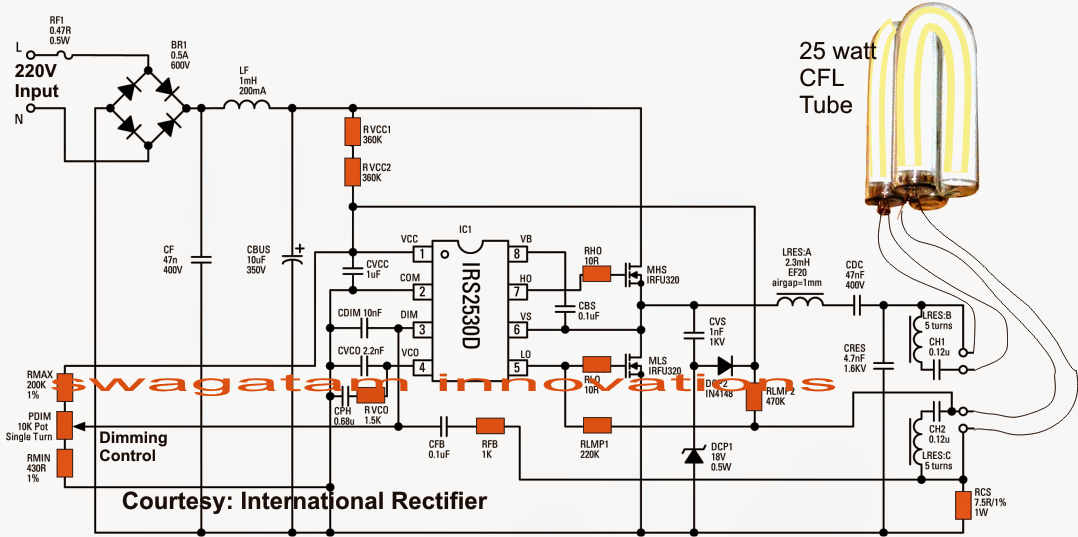
Single Chip Electronic Ballast Circuit with Dimmable Feature | Circuit

NEMA Premium Brand Now Includes High-Efficiency Fluorescent Electronic

(a) Electronic ballast and (b) its equivalent circuit. | Download

Electrical ballast - Wikipedia

(PDF) An improved Valley-Fill passive Power-Factor-Correction circuit

Electronic Ballast: Working Principle & Circuit Diagram | Electrical4U
